BLUE CARBON Lithium Battery and Inverter Communication: Step-by-Step Guide
A lithium battery and solar inverter must communicate correctly to ensure that the system charges, discharges and protects the battery within its permitted operating limits.
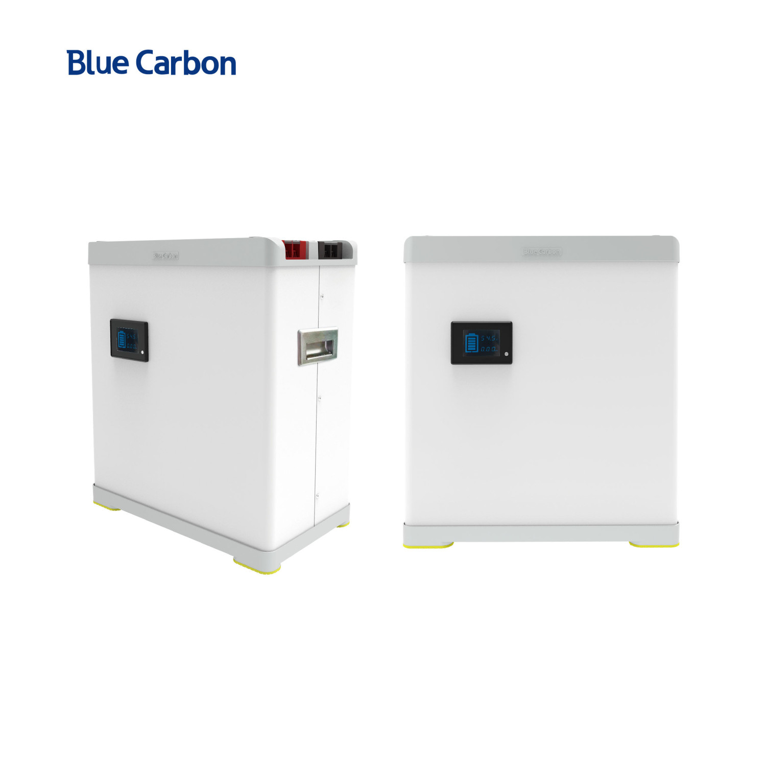
The BLUE
CARBON 15.36kWh-48V Stackable Lithium Battery with Smart BMS is designed with
an intelligent Battery Management System (BMS). The BMS monitors important
battery operating parameters, including voltage, current and temperature. When
connected to a compatible inverter with the correct communication settings, it
can help the inverter manage battery charging and discharging more effectively.
Blue Carbon
This guide
explains the installation checks, communication cable connection, inverter
settings and troubleshooting steps.

Product:
BLUE CARBON 15.36kWh-48V Stackable Lithium Battery with Smart BMS
View
the official BLUE CARBON product page
1.
Understand How Battery and Inverter Communication Works
The BMS is
the electronic protection and monitoring system inside the lithium battery. It
monitors battery conditions and helps protect the cells against unsafe
operating conditions.
Communication
between the battery and inverter allows the two devices to exchange information
such as:
- Battery voltage.
- Charging and discharging current
limits.
- State of charge (SOC).
- Battery temperature.
- Charging and discharging status.
- Battery protection and alarm
information.
Depending on
the battery and inverter models, communication may use CAN or RS485.
Important:
The product page confirms that this BLUE CARBON battery has Smart BMS
technology, but it does not publish the exact communication protocol, connector
pinout, baud rate or inverter-specific settings. These must be confirmed from
the battery's technical manual or BLUE CARBON technical support. Do not assume
that every RJ45 communication port uses the same wiring.
The
following is a practical installation procedure. The exact communication cable,
pin assignment and inverter menu names depend on the inverter model.
2. Identify the Battery and Inverter Communication Ports
Before
connecting anything, inspect the communication terminals on both devices.
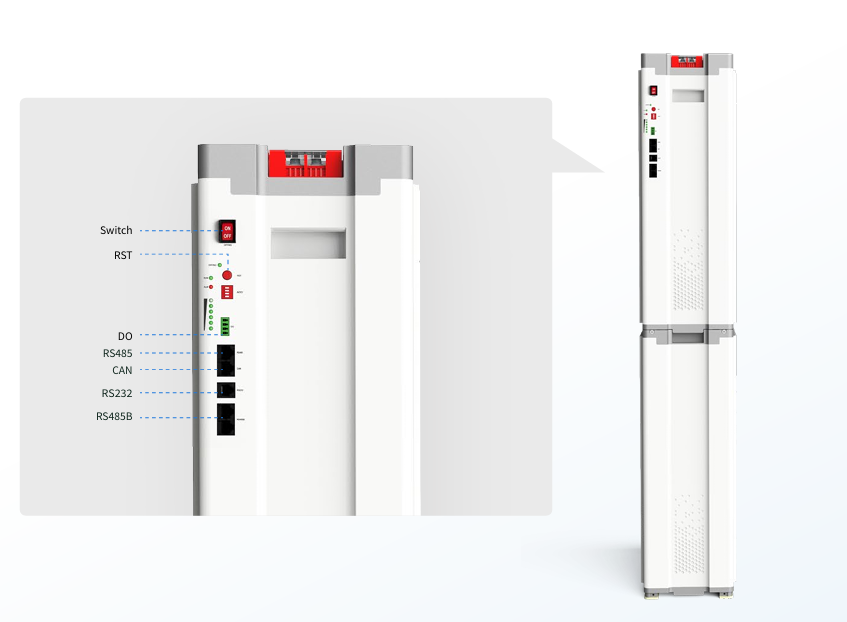
Common
labels include:
|
Port or
label |
Function |
|
CAN |
Controller
Area Network communication |
|
RS485 |
Serial
communication between battery and inverter |
|
BMS |
Battery
management communication interface |
|
LINK /
PARALLEL |
Communication
between multiple battery units |
|
ADD / DIP |
Battery
addressing or configuration, where provided |
Important
distinction: The battery's CAN/RS485 communication port is not the same as its
parallel communication port. Do not connect the inverter to a LINK or PARALLEL
port unless the manufacturer's wiring diagram specifically instructs you to do
so.
3.
Prepare the Equipment Before Installation
Ensure you
have the following:
- BLUE CARBON 15.36kWh-48V
stackable lithium battery.
- A compatible 48V lithium solar
inverter.
- Manufacturer-approved CAN or
RS485 communication cable.
- Correct battery power cables.
- Appropriate DC circuit breaker
or isolator.
- Insulated installation tools.
- Battery and inverter technical
manuals.
- Multimeter for electrical
checks.
Before
starting, switch off the inverter, isolate the solar PV input, disconnect the
grid or generator supply where applicable, and ensure the battery is safely
isolated according to the manufacturer's shutdown procedure.
Do not
connect or disconnect battery communication cables while the system is
energised unless the equipment manufacturer expressly permits it.
4. Connect the Battery Power Cables
Follow these
steps:
Step 1: Locate
the battery's positive (+) and negative (−) power terminals.
Step 2:
Identify the corresponding battery terminals on the inverter.
Step 3:
Confirm that the battery voltage matches the inverter's DC battery voltage
specification.
Step 4: Use
correctly sized battery cables and approved DC protection.
Step 5:
Connect the positive cable to the positive terminal and the negative cable to
the negative terminal, following the manufacturer's connection sequence.
Step 6: Check
the polarity and tighten all connections to the specified torque.
Step 7: Have
a qualified installer verify the voltage and connections before energising the
system.
Safety
warning
Never
reverse battery polarity. A wiring mistake can damage the inverter, battery or
both. Do not use an ordinary AC circuit breaker as a substitute for correctly
rated DC protection.
5.
Connect the Battery Communication Cable
This is the
most important step for enabling communication between the Smart BMS and
inverter.

Follow these
instructions:
Step 1:
Identify the communication protocol.
Check the
BLUE CARBON battery documentation to determine whether your particular battery
version communicates through CAN or RS485 with your inverter.
Step 2:
Identify the correct inverter communication port.
Locate the
corresponding CAN or RS485/BMS port on the inverter.
Step 3:
Obtain the correct communication cable.
Use the
cable approved for the particular battery and inverter combination. An ordinary
Ethernet cable may have the wrong pin arrangement even if its connector fits.
Step 4:
Confirm the pinout.
Check the
battery and inverter manuals for the exact connector pin assignments. Both ends
must be wired according to the approved cable diagram.
Step 5:
Connect the cable.
With the
equipment safely isolated, connect the battery communication port to the
inverter's designated BMS communication port.
Step 6:
Secure the connection.
Check that
both connectors are properly seated and that the cable is not damaged or
exposed to interference.
Do not guess
the RJ45 pinout or interchange CAN-H, CAN-L, RS485-A and RS485-B. Their wiring
is not necessarily interchangeable.
6.
Configure the Inverter Battery Settings

After
connecting the communication cable, configure the inverter.
The menu
names differ between manufacturers, but the general process is:
- Switch on the battery and follow
its startup procedure.
- Switch on the inverter according
to its manual.
- Open the inverter settings menu.
- Locate the battery type or
battery configuration option.
- Select the appropriate lithium
battery or BMS communication mode.
- Select the correct communication
protocol, CAN or RS485, as confirmed for the system.
- Select the correct battery model
or protocol profile if the inverter provides one.
- Save the settings.
- Check whether the inverter
recognises the battery.
Some
inverters require you to select a particular lithium protocol number rather
than simply choosing CAN or RS485.
Do not
select a random lithium protocol number. An incorrect protocol can cause
missing battery information or inappropriate charging and discharging limits.
7.
Confirm That the Battery and Inverter Are Communicating
Once the
configuration is complete, check the inverter display.

Depending on
the equipment, successful communication may display:
- Battery state of charge (SOC).
- Battery voltage.
- Charging current.
- Discharging current.
- Battery temperature.
- BMS charging and discharging
limits.
- Battery warning or protection
status.
For example,
the inverter may display a battery SOC of 75%.
This
indicates that the inverter is receiving battery charge information, provided
the displayed value is being supplied by the BMS rather than estimated by the
inverter.
A successful
communication check should also confirm that no BMS communication alarm is
present.
8.
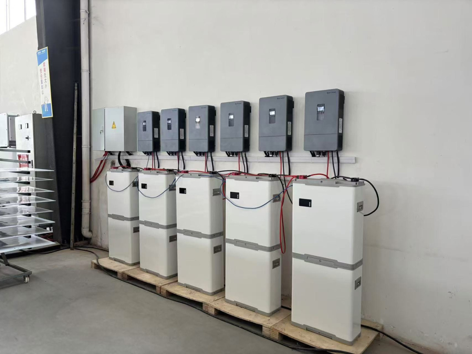
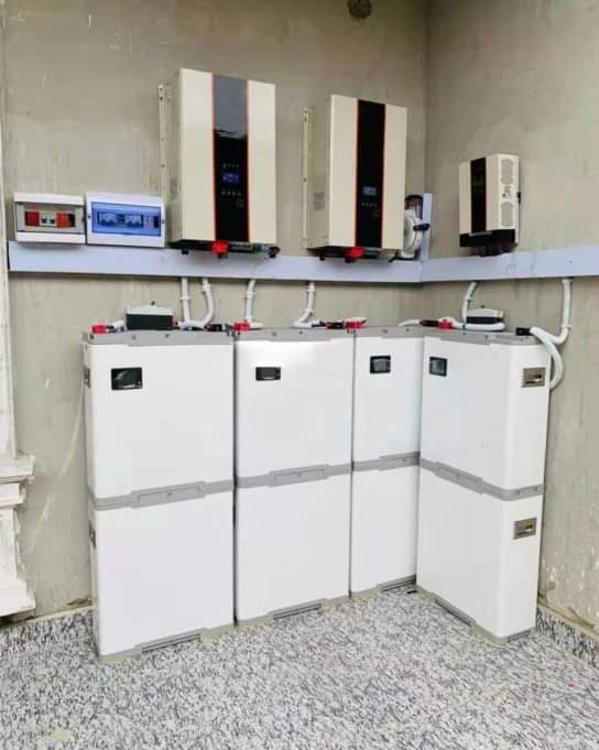
Configure Multiple BLUE CARBON Stackable Batteries
One of the
advantages of the BLUE CARBON battery's stackable design is the potential to
expand energy storage using compatible battery units. The product page
specifically states that expansion is subject to model compatibility and
manufacturer specifications.
Blue Carbon

When
installing multiple batteries, follow these general requirements:
- Confirm that the battery models
and firmware versions are approved for parallel operation.
- Follow the manufacturer's
instructions for power-cable connections.
- Connect the battery
communication or LINK cables using the specified topology.
- Configure battery addresses or
DIP switches if the model requires them.
- Identify the designated master
battery, if the system uses master-slave communication.
- Connect the master battery's
inverter communication port to the inverter's BMS port.
- Confirm that the inverter
recognises the combined battery bank.
- Verify that the total charging
and discharging limits are appropriate.
Important:
Do not assume that all stackable battery models use the same addressing system
or master-slave arrangement. The exact sequence, cable arrangement and address
settings must come from the relevant BLUE CARBON manual.
9.
Troubleshooting: When the Battery and Inverter Are Not Communicating
If the
inverter displays a BMS communication error or fails to recognise the battery,
check the following.
|
Problem |
Possible
cause |
What to
check |
|
BMS
communication error |
Incorrect
cable or protocol |
Verify
approved cable and protocol |
|
Battery
not detected |
Wrong
communication port |
Check
CAN/RS485 and BMS labels |
|
SOC not
displayed |
Communication
not established |
Check
cable pinout and inverter settings |
|
Battery
voltage displayed but no SOC |
Voltage-only
connection or failed BMS link |
Verify
communication mode |
|
Battery
alarm |
BMS
protection condition |
Check
battery alarm information |
|
Multiple
batteries not detected |
Incorrect
addressing or LINK connection |
Check
parallel configuration |
|
Charging
stops unexpectedly |
BMS limit
or protection event |
Check
charging limits and alarms |
Additional
troubleshooting checks
Check the
communication cable: A cable may fit physically but still have an incorrect pin
configuration.
Check the
protocol: Confirm that the inverter and battery are using the same supported
communication protocol.
Check the
inverter firmware: Some inverter models require a compatible firmware version
for specific battery protocols.
Check
battery startup: Follow the manufacturer's instructions for starting individual
batteries and the battery bank.
Check BMS
alarms: Investigate any battery protection warnings before attempting to
restart the system.
If
communication remains unsuccessful, stop repeated connection attempts and
request technical assistance. Do not bypass the BMS or force the inverter to
charge the battery.
10. What
If Your Inverter Does Not Support Battery Communication?
Some solar
inverters do not support CAN or RS485 communication with a particular battery.
In this
situation, voltage-based or user-defined battery operation may be possible, but
only if the battery manufacturer and inverter manufacturer approve it.
The
installer must obtain the correct:
- Bulk/absorption charging
voltage.
- Float charging voltage, if
applicable.
- Low-voltage cut-off.
- Maximum charging current.
- Maximum discharging current.
- Restart and recovery voltage.
- Battery temperature and
protection requirements.
These
settings must come from the exact battery and inverter manuals. Do not copy
settings from another lithium battery model.
Where
supported, the battery's internal BMS will continue providing cell-level
protection, but the inverter may not receive live SOC, current limits or other
BMS information.
11. Final
Commissioning Checklist
Before
handing the solar installation over to the customer, verify the following:
Installation
commissioning checklist
0/12
completed
Battery
model and inverter compatibility confirmed
Battery
voltage and polarity verified
Battery
power cables correctly installed
Correct DC
protection installed
Approved
CAN/RS485 communication cable used
Communication
pinout verified from manuals
Correct
lithium protocol selected on inverter
Battery SOC
displayed correctly
Charging and
discharging limits verified
No active
BMS or inverter alarms
Multiple
battery addressing checked, where applicable
System
tested under charging and load conditions
Copy
commissioning checklist
12.
Important Technical Information to Confirm with BLUE CARBON
The product
page confirms Smart BMS functionality, but does not publish the detailed
inverter communication instructions. Before preparing a model-specific wiring
diagram or installer training document, obtain confirmation of the following:
|
Technical
detail |
Confirmation
required |
|
Battery
communication protocol |
CAN, RS485
or both |
|
Battery
communication connector |
Exact port
identification |
|
Communication
pinout |
RJ45
pin-by-pin wiring |
|
Communication
cable |
Approved
cable type |
|
CAN
settings |
Baud rate
and protocol |
|
RS485
settings |
Baud rate,
parity and address |
|
Inverter
compatibility |
Approved
inverter brands and models |
|
Parallel
configuration |
Master/slave
and addressing procedure |
|
Charging
limits |
Maximum
permitted charge/discharge current |
|
Firmware |
Compatible
battery and inverter versions |
For official
technical assistance, contact:
BLUE CARBON
NIGERIA
- Website: https://bluecarbon.ng/
- Product: 15.36kWh-48V
Stackable Battery with Smart BMS
- Telephone: 09042103985
- Email: enquires@bluecarbon.ng
Tags:
Blue Carbon lithium battery inverter communication, lithium battery BMS
communication, CAN communication solar inverter, RS485 lithium battery
connection, Blue Carbon 15.36kWh battery
Recent Posts
BLUE CARBON Lithium Battery and Inverter Communication: Step-by-Step Guide
Best Solar Energy Company in Nigeria: What Should You Look For?